
Fire Pump Room Layout and Design for Firefighting Systems
January 14, 2026The design of the fire pump room is a fundamental and pivotal element in fire fighting systems, as this room plays a crucial role in ensuring the efficiency and continuity of pumping water to the fire network when needed.
The design of the pump room requires adherence to a set of precise standards and requirements based on approved international codes, such as the NFPA code, in order to provide a safe and efficient operating environment for the pumps and all supporting equipment.
In this article, we highlight the most important considerations and technical specifications that must be taken into account when designing a fire pump room, in order to ensure the highest levels of safety and reliability.
Fire pump room
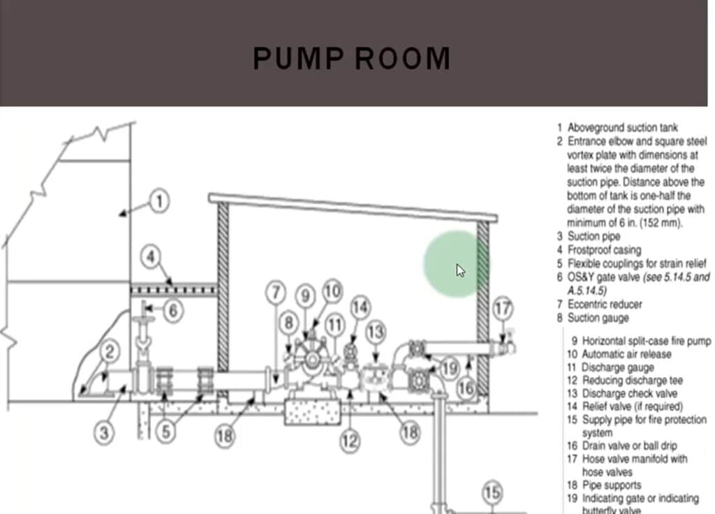
The diagram is a design that shows you the components and design of a fire pump room. In this section, we will explain in detail the most important main components in this diagram:
- The tank used in fire systems represents:
- The VORTEX PLATE is a part that is fitted onto the intake pipe that takes in water and beginsBy feedingThe fire pump shown to you as number 9 in the drawing is important because it prevents the accumulation of eddies that lead to cavitation on the suction line.
- The SUCTION PIPE represents the suction line that carries water from the tank to the pump.
- FROSTPROOF CASING is a covering that prevents water in pipes from freezing in cold environments.
- FLEXIBLE COUPLING is used to prevent the transmission of vibrations from the pump and motor to the suction line, thus maintaining system stability.
- It represents an isolation valve that is installed on the suction line to control the flow of water.
- It stands for ECCENTRIC REDUCER and is used on the suction line where the diameter of the pump flange is smaller than the diameter of the suction line.
- Pressure gauges and parts number 8 and 11 represent the pressure fittings that are installed on the pump's suction and discharge lines.
- The PUMP is the basic element in the system that pumps water to the fire department network.
- The AUTOMATIC AIR VENT is installed on the pump to remove excess air.
- The CHECK VALVE is mounted on the discharge line to ensure that water flows in only one direction.
- RELIEF VALVE is used in the case of a diesel engine-powered fire pump to relieve pressure.
This was an overview of the fire pump room design components from United Group, the exclusive agent for Watex UAE in Egypt.
Read more about: ul fm approved fire pumps
Fire pump installation instructions
Fire pumps are the essential component of an automatic sprinkler system that supplies fire sprinklers. These pumps operate using various power sources such as electricity, diesel, or steam, and are typically connected to a constant water supply. The pump's suction line is connected to a fixed water source such as a water tank.
The pump's function is to deliver a high-pressure water stream to the vertical pipes connected to the sprinklers and fire hoses. These pumps undergo rigorous inspection and testing by internationally recognized agencies such as UL and FM to ensure their quality and effectiveness.
Fire pumps can be powered either by an electric motor or a diesel engine, and in some cases steam turbines can be used.
The fire pump starts working when the pressure drops significantly in the automatic sprinkler system, which occurs when fire sprinklers are exposed to temperatures exceeding their design limit.
This causes them to open automatically and allow water to pass through. Also, opening water hose reels or other fire-fighting connections leads to a drop in pressure in the pipe network.
During a fire, the Jockey Pump starts working to compensate for the loss of pressure within the network, but only if the drop in pressure is large and the required flow rate is greater than the capacity of the Jockey Pump.
This pump stops working and the main electric pump starts working to provide the required flow and pressure in the system. The main pump continues to work until the required goal is achieved. If the electric pump fails to provide the necessary pressure and flow or if a power outage occurs, the diesel pump takes over automatically and does not stop except by manual shutdown.
Best types of fire pumps
The fire pumps launched by United Group, the exclusive agent for the UAE-based Watex company in the Egyptian market, have received great praise from many institutions thanks to their precise design in accordance with international and local standards, which ensures the highest levels of efficiency in pumping water and extinguishing fires.
The best types of fire pumps offered by United Group include the following:
- Electric Pump
- The design of the fire pump room is based on reducing pressure within the system, allowing water to flow in the appropriate quantity and pressure to meet the needs of the fire extinguishing network.
- Diesel Pump
- The diesel pump shares the same specifications and operating mechanism as the electric pump, but it usually starts working when there is a power outage.
- Jockey Pump
- The jockey pump is used as a compensatory pump to compensate for any slight decrease in water pressure resulting from leaks in the network, where it pumps water at a rate of 10-15% of the total capacity at high pressure to maintain the stability of the system.
You can contact us at Al-Muttahida Company, the exclusive and sole agent for Watex UAE in Egypt, via phone numbers or through our website to obtain the best types of fire pumps to protect your facility from the risk of fire.
Fire pump room specifications
Overview of the specifications and design of a fire pump room
- Main Pump
- Standby Pump
- Jockey Pump
- How pumps work:
- The main pump is responsible for supplying the network with the required pressure and flow rate according to the system design. In the event of a fire, only one pump will start operating, and that is the main pump if it is functioning correctly.
- The backup pump operates automatically in the event of any malfunction or failure in the main pump, to ensure the continued supply of the network with the required pressure and flow rate.
- A jockey pump is a compensatory pump that operates when a leak occurs in the network, and its purpose is to maintain constant pressure in the system. Its pressure is set to be equal to or slightly higher than the main pump pressure, but with a flow rate equal to 10% of the main pump's flow rate.
- Control system:
- The fire pump room is designed so that each pump has its own control panel containing a pressure switch. A line from the discharge of each pump, called the sensing line, is connected to the pressure switch on the control panel. A single pipe from the discharge head can be used for all pumps.
- Operating mechanism:
- Assuming the network pressure is 10 bar, for example, and in the event of a leak, the pressure in the network drops, so the jockey pump starts working to compensate for the loss.
- In the event of a fire, the sprinklers activate, further reducing the water pressure. The jockey pump kicks in, but if it cannot supply the required amount of water, the main pump kicks in to compensate for the pressure and water loss in the system. If the main pump fails to operate for any reason, the backup pump kicks in.
- Additional specifications:
- All fire pumps are of the centrifugal type.
- The jockey pump is always equipped with an electric motor.
- The main and backup pumps canTurning them onIt is powered by an electric motor, but in case of fire or power outage, the backup pump will not function. Therefore, it is preferable for it to have an alternative power source to the main pump.
- The backup pump can be operated either by the building's own generator or by using a diesel engine, which is the more common solution. In some special facilities such as petroleum companies, the backup pump is supplied with its own generator.
- Jockey pump design:
- Jockey pumps are often of the vertical type and multi-stage, because they require high pressure to compensate for pressure loss.
- Fire water tank:
- The fire water tank is often concrete and divided into two parts. A separate suction line is used for each part. This line includes a strainer and an OS&Y type gate valve, and is then connected to the pump suction head.
- Draw line calculation:
- The volume of the suction line from the tank can be calculated using the equation Q = V × A, assuming a flow rate of 2 meters per second.
Learn more about: Types of fire extinguishers
Fire pump room components
This fire pump room design is not a core component but is designed and implemented by other parties within the fire pump room:
- Pump Base
- Concrete foundations designed and constructed by the structural engineer to mount the pumps on them.
- Pump Room Access
- Each pump room must have two entrances, one to enable maintenance personnel and technicians to enter and exit, and the other to facilitate the lowering of heavy equipment and engines.
- Trench and Floor Drain
- These are the ground drainage points that collect the leaked water in the pump room. The water is collected in a small tank called a septic tank, where submersible pumps are installed. These pumps operate automatically when the floats reach a certain water level, via signals sent by the control panels, because the level of the pump room is usually lower than the main drainage network, which necessitates the use of this method.
- Overhead Crane
- Used in large pump roomsTo moveHeavy components.
- Exhaust Fan
- It works by constantly renewing the air inside the pump room to ensure good ventilation.
Fire pump room design
The design of a fire pump room is one of the most important elements within fire protection systems, as a range of factors are taken into account to ensure the efficiency and safety of the system. Here are the most important elements for designing a fire pump room.
- Location and area
- The pump room should be located away from sensitive and dangerous areas of the building and have sufficient space to facilitate access to the pumps for routine maintenance. It is also preferable for the room to be close to the water source to reduce pressure loss.
- Pump Room Access
- The room must have multiple entrances, one for personnel and technicians to enter for maintenance, and another for heavy equipment or engines to enter in case some parts need to be replaced or repaired.
- ventilation
- The pump room must be equipped with a good ventilation system to constantly renew the air and prevent high temperatures inside the room.
- Pump Base
- A concrete base is built under each pump to ensure its stability and reduce vibrations. The base must be designed to bear the weight of the pumps and take into account the appropriate distribution of loads.
- Drainage System
- The fire pump room is designed with a drainage system that includes trench and floor drains, where excess or leaking water is collected in a small tank called a septic tank, and a submersible pump is used to drain it automatically.
- Overhead Crane
- In large rooms containing heavy equipment, an overhead crane is installed to facilitate the transfer and movement of heavy equipment inside the room, such as engines or large pumps.
- Basic components of pumps
- The room must contain the Main Pump, the Standby Pump, and the Jockey Pump, each pump performing a specific function in different situations.
- Basic electricity for pumps
- The fire pump room is designed with isolated electrical systems to operate the pumps, with control panels for each pump. These panels must contain pressure switches to control the automatic operation of the pumps according to the pressure condition within the network.
- Insulation and fire protection system
- It is preferable to use heat and moisture insulation materials in the design of walls and floors, along with providing self-extinguishing systems inside the room for protection in case of a fire.
- water tank
- The water tank should ideally be designed to be close to the pump room to ensure a continuous water supply. The tank is divided into two parts with an independent suction line for each part to ensure a continuous water supply to the pumps.
The design of a fire pump room depends on meeting performance and efficiency requirements to ensure the system's continued operation in emergencies, and it is essential to comply with international and local standards to ensure the safety of individuals and the building.
How is the volume of a fire tank calculated?
Let's assume we have a fire pump with a capacity of 500 gallons per minute in a medium hazard rating. The water tank capacity is calculated based on an operating time of 60 minutes, which is usually sufficient to provide the necessary water for firefighting operations.
In the case of mild risk, the time is calculated based on 30 minutes, while in the case of high risk, it is calculated based on 90 minutes.
Accordingly, the volume of the water tank for the fire suppression system is calculated as follows:
Water tank volume = Flow rate × Operating time × Gallons to liters conversion factor
= 500 gallons/minute × 3.785 liters/gal × 60 minutes
= 113,550 liters
To convert the volume to cubic meters, divide by 1000:
Water tank volume = approximately 113.5 cubic meters
Therefore, the required capacity for the water tank in the case of medium risk is approximately 113.5 m³.
Read also about: Fire fighting pump prices

How to calculate the capacity of a fire pump?
If the required pressure is 7 bar and the flow rate is 1000 gallons per minute (GPM), then a pump capable of achieving a flow of 1000 GPM at a pressure of 7 bar must be selected.
The pump must also maintain its ability to pump 1500 GPM when the pressure drops to 65% of the rated pressure, which is approximately 4.5 bar. Contact us to inquire about the design of a fire pump room.
Fire network design
United Group, the exclusive agent for Watex UAE in Egypt, provides comprehensive consulting and engineering services for all fire pump room systems and design through a highly trained and qualified team to carry out the following tasks.
- Design of automated alarm and fire suppression systems using water sprinklers.
- Design of automatic alarm and fire suppression systems using carbon dioxide gas.
- Design of automatic alarm and fire suppression systems using FM200 gas.
- Design of automated alarm and fire suppression systems for kitchens.
- Design of automated alarm system networks using the conventional method (Conventional Systems)
- Designing automated alarm system networks using the Addressable Systems method.
- Designing pump rooms and selecting suitable fire pumps.
- Design of fire piping networks using seamless pipes orH.D.P.E - UPVC
Fire network components
The fire pump room and fire network are carefully designed to ensure that all components work together perfectly. Here are the main components of the fire network:
- The voice alarm system: It is the first component of the fire network, as it alerts individuals inside the building to the presence of a fire so that they can evacuate the place quickly.
- Firefighting equipment: such as automatic sprinklers, which are an important part of fire control.
- Supply pipes and drainage networks: These deliver water and fire-fighting materials to the required locations.
- Automatic sprinklers: sensitive to heat and operate automatically when temperatures rise to release water in multiple directions to limit the spread of fire.
Some fire suppression systems rely on non-water extinguishing agents such as carbon dioxide, nitrogen, or helium, as these gases react with the fire and contribute to the extinguishing process effectively.
Fire alarm system companies
United Group, one of the best fire alarm systems companies in the Egyptian market, offers the best fire fighting devices that protect property and individuals, thanks to its extensive experience in selecting the appropriate systems for each application while adhering to all international standards.
The company has implemented large projects including hospitals, malls, administrative buildings, large factories, and residential buildings according to international and local specifications. United Company is distinguished from other companies in this field by providing fire pump room design, supply, maintenance, installation, and supervision of implementation services.
United Company also has a dedicated maintenance department, equipped with the latest tools and equipment necessary for servicing all types of fire extinguishers and firefighting equipment. The team consists of highly experienced and qualified technicians and engineers specializing in fire pump room design, enabling them to meet all maintenance needs wherever required.


